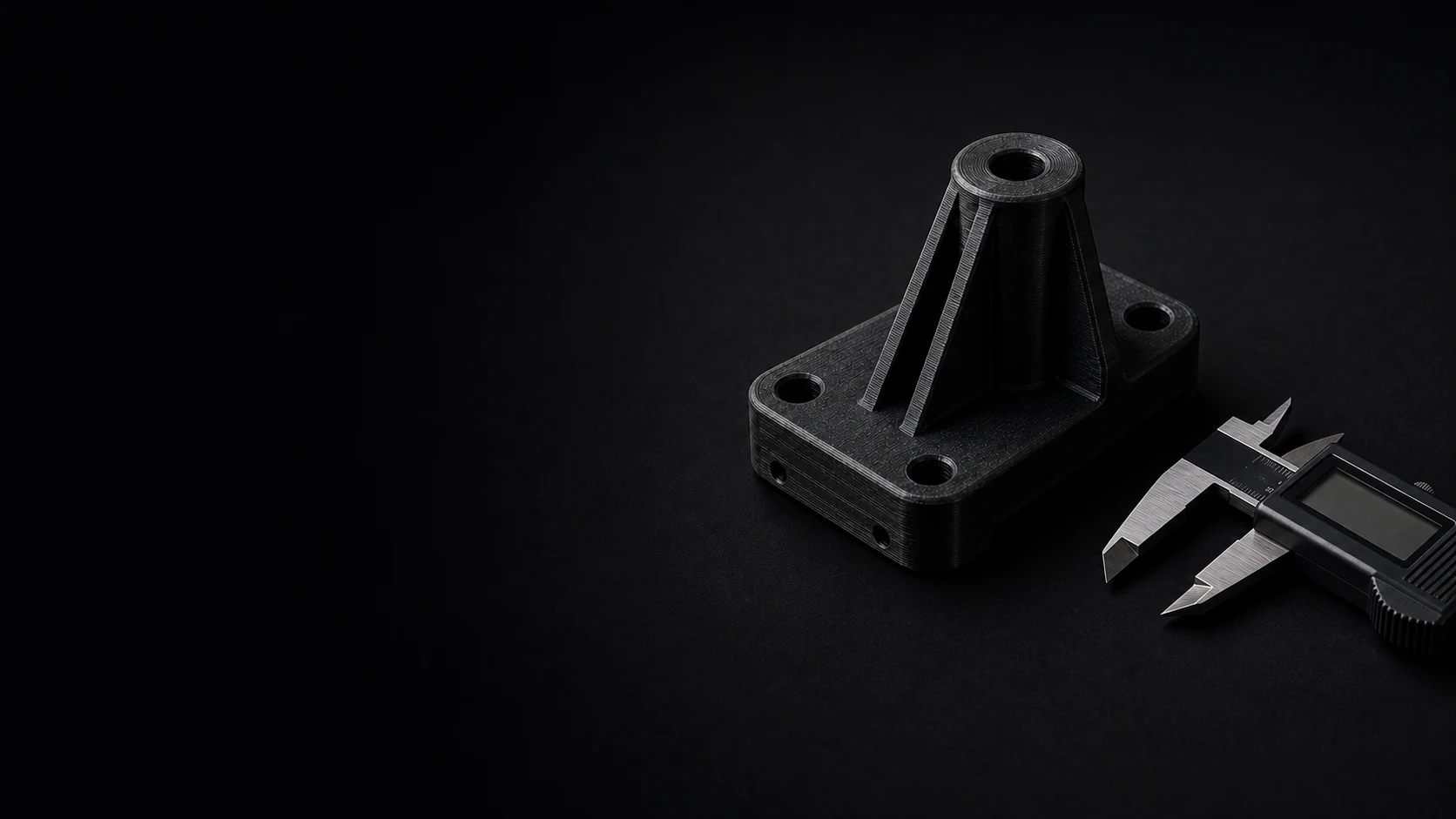
The practical starting point
Start with the limits that change the order.
Part size, fit, and surface expectations have the biggest effect on whether a file can move straight into production.
01 /
Part size
220 x 220 x 250 mm
Our current service is built around a maximum single-part envelope of 220 x 220 x 250 mm (8.66 x 8.66 x 9.84 in). If your model is close to the limit, keep in mind that orientation matters. A part may fit in one orientation and not in another.
More guidance
- Smaller parts usually quote faster, print more consistently, and ship more economically.
- Tall, thin parts can be printable but may need more conservative geometry to avoid wobble or layer shift risk.
- If a part is oversized, it can often be redesigned into multiple interlocking or fastened sections.
02 /
Tolerance + fit
+/- 0.25 mm typical
For general FDM service work, a realistic expectation is +/- 0.25 mm (+/- 0.010 in) on many dimensions, with looser variation on larger parts, long flat spans, thin walls, and features sensitive to cooling or shrink behavior.
More guidance
- Press fits, bearing pockets, sliding fits, and gasket surfaces should be designed with testing and adjustment in mind.
- Critical fit features often benefit from a small amount of post-processing or a printed test coupon first.
- If a dimension is truly critical, call it out early so the design can be reviewed before production.
03 /
Printed finish
Functional, not injection-molded
Our standard service is tuned for strong, clean, functional parts rather than cosmetic showroom perfection. Expect visible layer lines, especially on curved surfaces, shallow angles, and large radiused faces.
More guidance
- Vertical walls usually present the cleanest visual finish.
- Carbon-fiber-filled materials typically look more matte and hide layer lines a bit better than standard materials.
- Top surfaces, hole walls, underside overhangs, and unsupported bridges are the areas most likely to show process texture.
Technical settings
Production profile
Use these values as practical design guidance. Geometry, orientation, material, and load direction still affect the finished part.
View every technical specification
- Default service profile
- 0.24 mm layers / 0.0094 in
- Nozzle diameter
- 0.6 mm / 0.024 in
- Recommended minimum wall
- 1.2 mm / 0.047 in
- Recommended robust wall
- 1.8 to 2.4 mm / 0.071 to 0.094 in
- Recommended clearance for moving/sliding fit
- 0.3 to 0.5 mm / 0.012 to 0.020 in
- Recommended clearance for easy assembly
- 0.2 to 0.3 mm / 0.008 to 0.012 in
Design guidance
Design for the load, fit, and hardware.
A printable file is not always a durable part. These decisions have the biggest effect on performance.
01 /
Layer direction
Keep pull and bending loads away from weak layer boundaries.
02 /
Walls + transitions
Use 1.8 to 2.4 mm walls for robust parts, add ribs where useful, and fillet sharp internal corners.
03 /
Mating parts + hardware
Add clearance intentionally and plan for inserts, captured nuts, or finished holes when repeatable assembly matters.
Design principles for strong, printable custom parts
Design with layer direction in mind
FDM parts are anisotropic. They are usually strongest along the printed roads and weaker across layer boundaries. If a part will be loaded in bending, impact, or pullout, try to orient the geometry so the layer lines do not become the failure plane.
Give walls and ribs real substance
Ultra-thin walls may quote and print, but they are more likely to warp, ring, or feel fragile. A wall that looks acceptable in CAD can still be too light for a durable real-world part.
Add clearance to mating parts
Do not model two printed parts or a printed part and a purchased part at exactly nominal size and expect perfect assembly. Clearance should be designed in intentionally.
Avoid huge flat spans when possible
Large flat plates and lids can curl, distort, or telegraph internal stresses. Ribs, chamfers, shallow curves, and segmented geometry often print better than big uninterrupted flats.
Use fillets and generous transitions
Sharp internal corners concentrate stress and can reduce print reliability. Smooth transitions improve both part strength and print stability.
Plan for real hardware
Threads, inserts, screws, snaps, and shafts all behave differently in printed plastic than they do in machined metal. Where practical, design around heat-set inserts, captured nuts, or post-machined holes for the most reliable assemblies.
Strong fit
Where FDM works best
- Fast prototypes
- Fixtures and jigs
- Brackets and mounts
- Housings and adapters
- Low-volume production
Call it out early
When to flag the risk
- Precision fits
- High heat
- Large thin panels
- Cosmetic show surfaces
- Strength across layers
Review detailed process strengths and tradeoffs
Process strengths
- Fast turnaround without tooling
- Low cost for one-offs and short runs
- Excellent for complex geometry and internal features
- Easy to iterate between revisions
- Great for fixtures, brackets, enclosures, jigs, prototypes, and custom adapters
Process tradeoffs
- Not ideal for mirror-smooth cosmetic surfaces straight off the printer
- Dimensional accuracy is good but not the same as precision machining
- Layer-based process means strength depends on orientation
- Large, thin, and heat-sensitive geometry can distort more than simple compact parts
- Some features still benefit from drilling, reaming, tapping, sanding, or inserts after printing
Review the complete technical specification table
| Specification |
Current service |
| Default service profile |
0.24 mm layers / 0.0094 in |
| Nozzle diameter |
0.6 mm / 0.024 in |
| Recommended minimum wall |
1.2 mm / 0.047 in |
| Recommended robust wall |
1.8 to 2.4 mm / 0.071 to 0.094 in |
| Recommended clearance for moving/sliding fit |
0.3 to 0.5 mm / 0.012 to 0.020 in |
| Recommended clearance for easy assembly |
0.2 to 0.3 mm / 0.008 to 0.012 in |
| Minimum embossed/debossed detail |
0.6 to 0.8 mm / 0.024 to 0.031 in |
| Safer text height/depth |
1.0 mm+ / 0.040 in+ |
| Unsupported bridge guidance |
Keep short whenever possible; test if appearance matters |
| Overhang guidance |
Gentler angles produce cleaner undersides |
Upload the file. We’ll check the practical limits.
Review pricing before checkout, or ask for a paid part review when the design still needs work.
Need a deeper answer?
Match the requirement to the right next page.